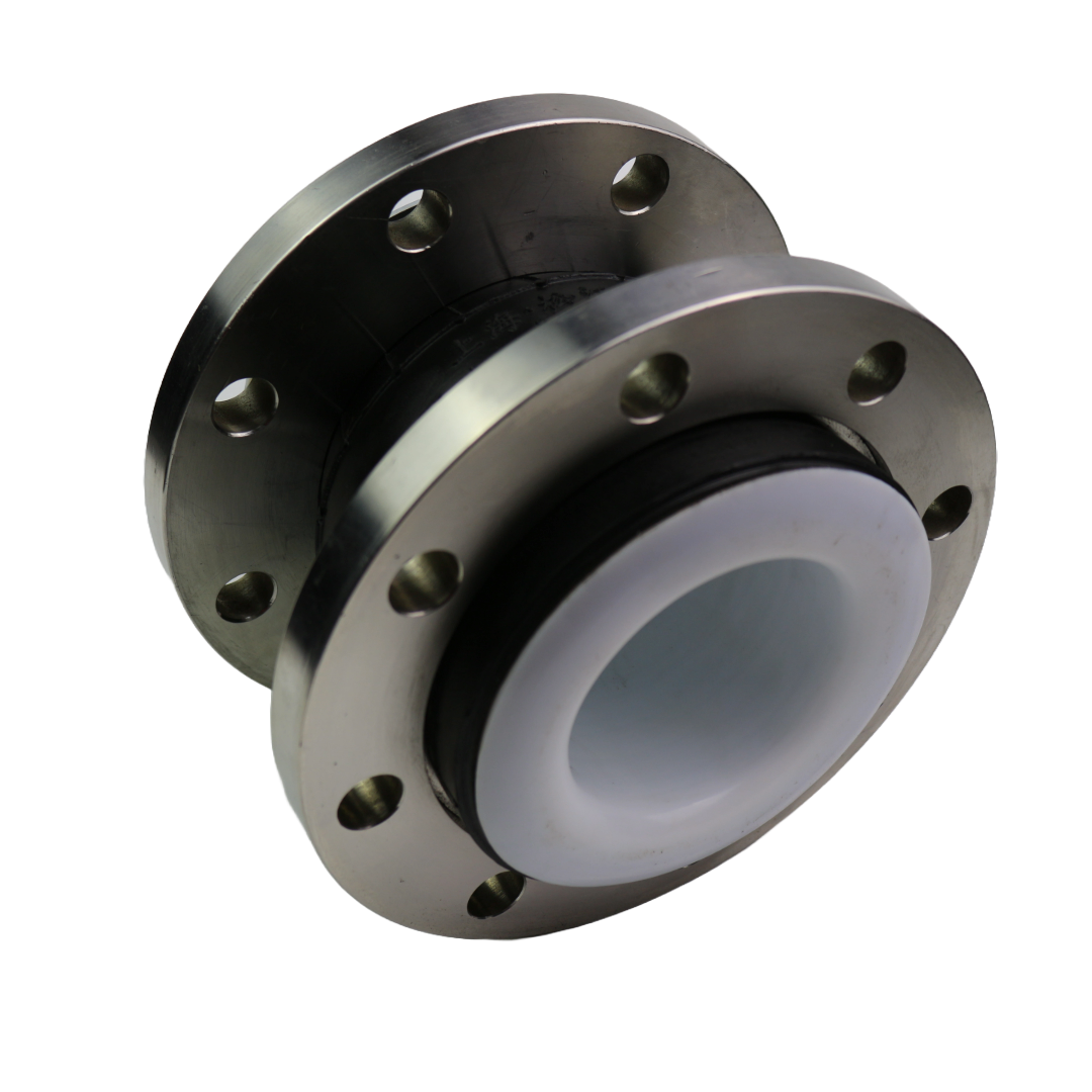
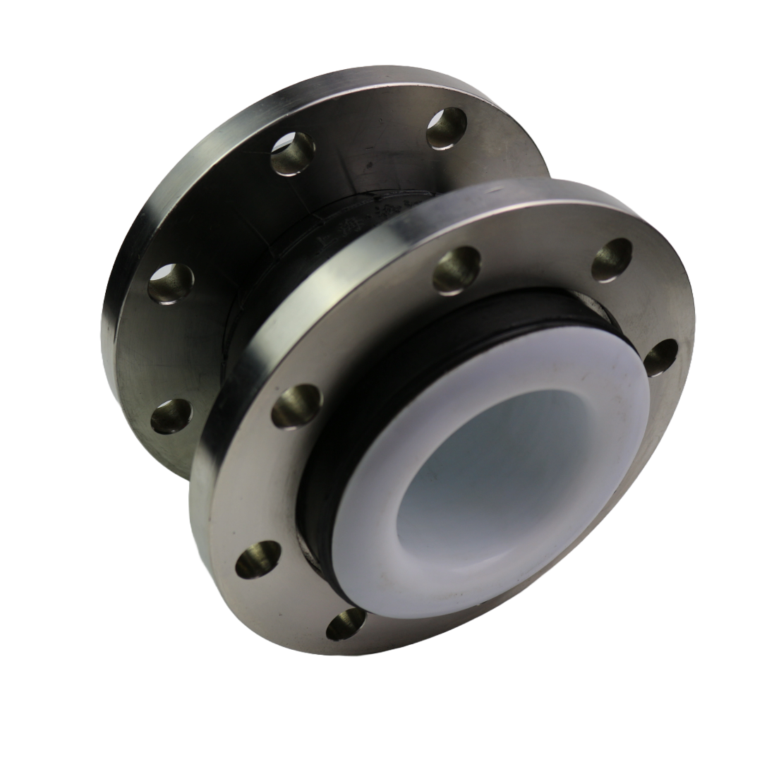
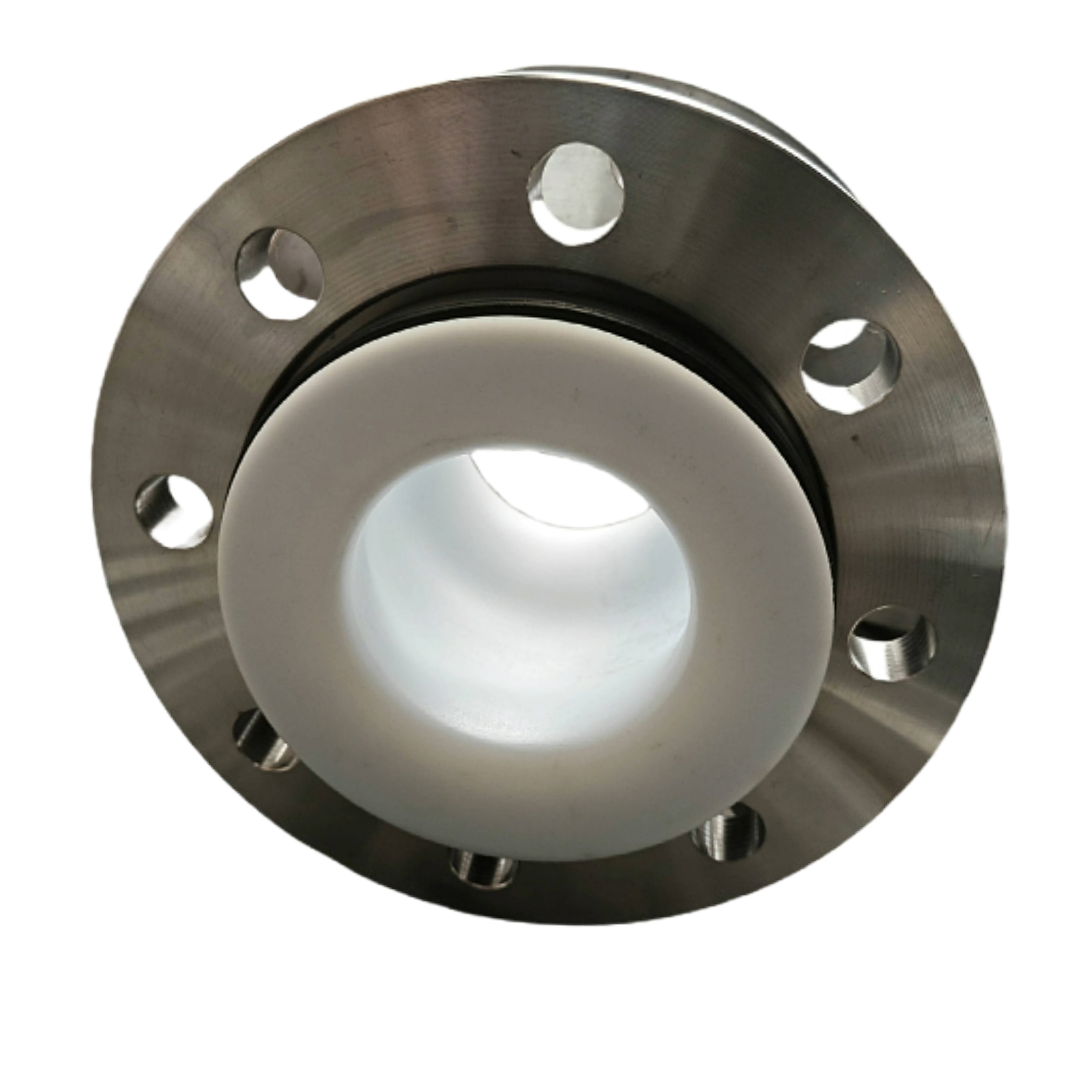
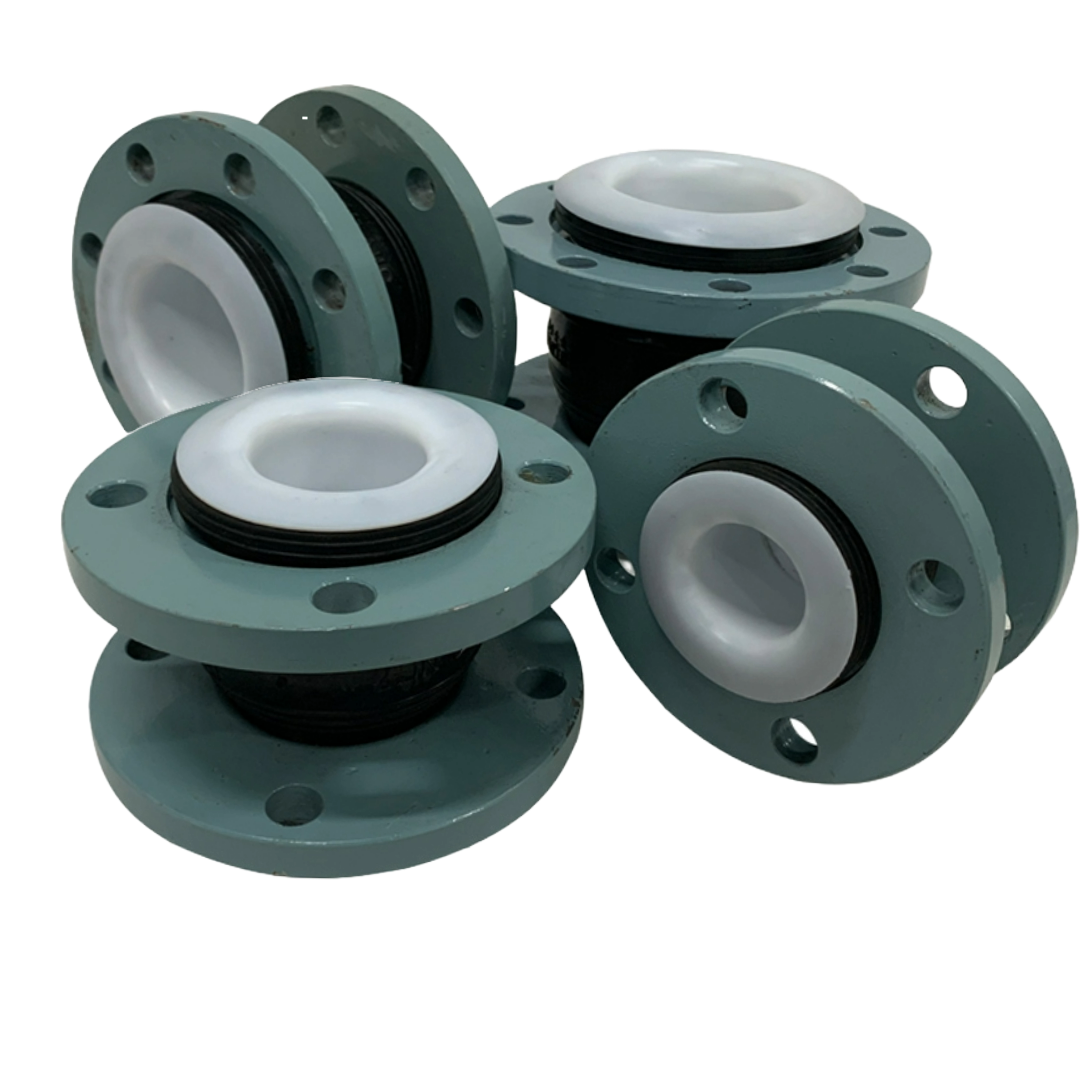
PTFE Lined Rubber Expansion Joint
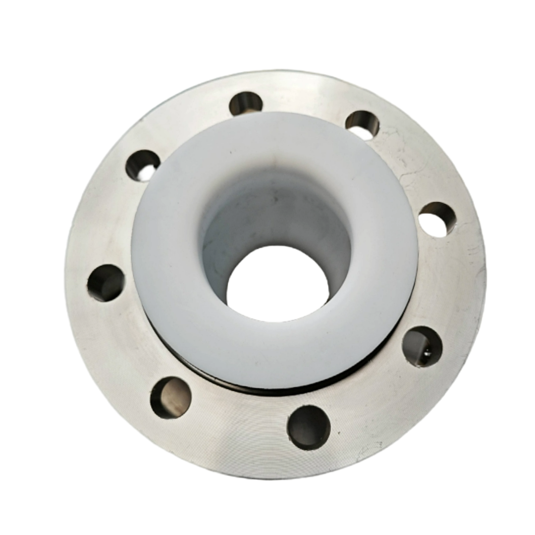
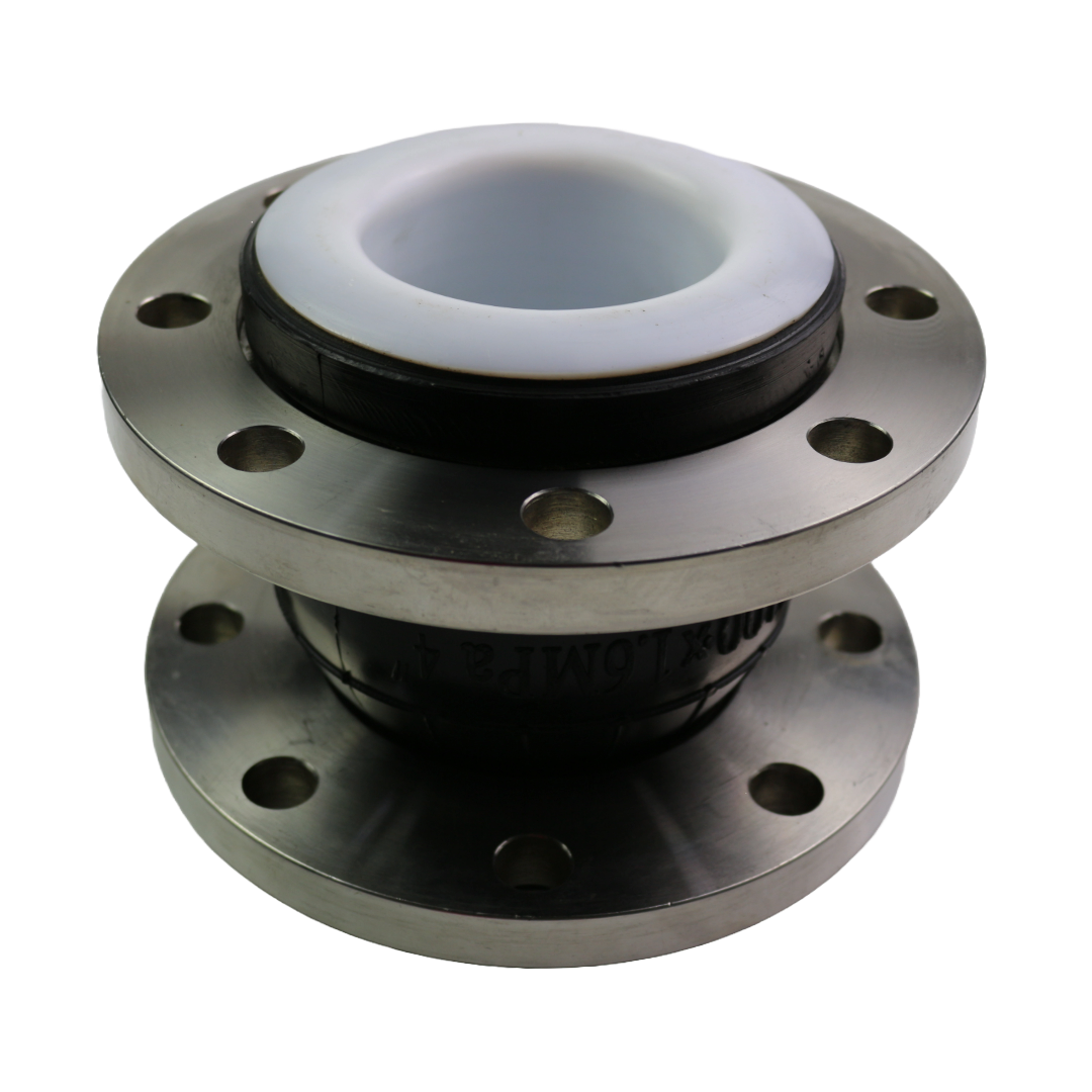
Hongze PTFE Lined Rubber Expansion Joint is a flexible flanged connector developed for corrosive chemical pipelines where direct contact with an ordinary rubber lining may not provide adequate media resistance. A PTFE wetted liner isolates the reinforced rubber body from the process fluid, while the flexible construction helps absorb vibration, reduce structure-borne noise and accommodate limited axial, lateral and angular movement.
This chemical-resistant rubber expansion joint is commonly evaluated for acids, alkalis, corrosive wastewater, chemical-processing fluids, electroplating solutions and other aggressive media. PTFE has broad chemical resistance, a smooth low-friction surface and low contamination tendency; however, no material should be described as universally compatible. The exact chemical name, concentration, temperature, pressure, vacuum, solids and cleaning procedure must be reviewed before selection.
Standard catalog dimensions cover DN32 to DN1200. Larger diameters, special face-to-face lengths, flange drilling, PTFE liner construction, rubber body material, vacuum reinforcement and control units can be evaluated from project drawings. Large-diameter feasibility depends on pressure, vacuum, movement, transport limits, flange strength and installation conditions.
Key Features and Benefits
- PTFE wetted liner protects the rubber body from direct contact with compatible corrosive media.
- Suitable for many acid, alkali and chemical services after application-specific compatibility review.
- Smooth PTFE surface helps reduce product adhesion and facilitates cleaning compared with many elastomer surfaces.
- Flexible rubber body helps isolate vibration from pumps, compressors and process equipment.
- Reduces structure-borne noise transmitted through rigid piping.
- Compensates limited axial extension, axial compression, lateral displacement and angular deflection.
- Helps reduce mechanical loads transferred to pumps, valves, vessels and connected equipment.
- Standard catalog dimensions from DN32 to DN1200.
- Large diameters above DN1200 can be evaluated from drawings and complete operating data.
- Available with carbon steel, galvanized steel, stainless steel 304 or stainless steel 316/316L flange options.
- ASME/ANSI, EN, DIN, JIS, BS, GB, HG and drawing-specific flange drilling can be evaluated.
- Custom liner thickness, body length, reinforcement and movement-limiting arrangements are available after engineering confirmation.
General Product Specifications
| Specification | Standard or Available Option |
|---|
| Product name | PTFE Lined Rubber Expansion Joint |
| Alternative names | PTFE Lined Rubber Joint, PTFE Lined Flexible Connector, Chemical Resistant Rubber Expansion Joint |
| Nominal size range | Catalog dimensions DN32-DN1200; larger diameters subject to project review |
| Wetted lining | PTFE liner with project-specific construction and thickness |
| Rubber body options | EPDM, Natural Rubber, Neoprene/CR, IIR, NBR or application-specific compound |
| Reinforcement | Textile cord layers and reinforced bead/end areas; vacuum reinforcement when required |
| Connection | Flanged ends |
| Flange materials | Carbon steel, galvanized carbon steel, stainless steel 304 or stainless steel 316/316L |
| Flange standards | ASME/ANSI, EN, DIN, JIS, BS, GB, HG or approved custom drilling |
| Pressure rating | Selected according to DN, temperature, liner design, rubber body, flange rating, vacuum and movement |
| Temperature rating | Determined by the complete assembly; PTFE resin temperature capability is not the finished-joint rating |
| Movement | Axial extension, axial compression, lateral displacement and angular deflection within approved combined limits |
| Typical media | Compatible acids, alkalis, chemical solutions, corrosive wastewater and process fluids |
| Typical industries | Chemical processing, wastewater treatment, electroplating, pharmaceutical, fertilizer, mining and industrial utilities |
| Customization | Diameter, length, liner, reinforcement, flange, drilling, control units, marking, testing and documentation |
Critical engineering note: PTFE resin may retain useful properties at temperatures far above the rating of many rubber compounds, but the allowable temperature of a PTFE lined rubber expansion joint is controlled by the complete assembly. Rubber body, liner forming method, pressure, vacuum, movement, flange connection, cycle frequency and process medium must all be considered. Never apply a PTFE resin temperature limit directly to the finished expansion joint.
How the PTFE Lined Construction Works
| Layer or Component | Function | Selection Requirement |
|---|
| PTFE wetted liner | Forms the primary chemical barrier between the process medium and rubber body | Confirm chemical, concentration, temperature, pressure, vacuum, permeation and cleaning conditions |
| Inner support layer | Supports the liner and transfers movement into the reinforced rubber structure | Construction must suit liner thickness, pressure and movement requirements |
| Reinforced rubber body | Provides flexibility, vibration isolation and pressure-carrying structure | Select compound and reinforcement for external environment and operating conditions |
| Textile cord reinforcement | Controls body deformation and carries pressure loads | Layer quantity and orientation depend on size, pressure and vacuum |
| Bead or wire reinforcement | Stabilizes the flange and end-sealing area | Must match flange geometry and pressure forces |
| Metal flanges | Connect the flexible body to the pipeline | Material, drilling, facing and rating must match the mating system |
The PTFE liner must remain continuous and undamaged through the wetted area and sealing surfaces. Liner wrinkles, cuts, excessive stretching, vacuum collapse or incorrect flange compression can compromise service performance. The final liner configuration and thickness should be confirmed on the production drawing rather than selected from a generic value.
PTFE Lined vs. Unlined Rubber Expansion Joint
| Comparison | PTFE Lined Rubber Expansion Joint | Unlined Rubber Expansion Joint |
|---|
| Wetted surface | PTFE chemical barrier | Selected elastomer is directly exposed to the medium |
| Chemical service | Broad chemical applicability after compatibility review | Limited by the exact EPDM, NBR, CR, NR, IIR or FKM compound |
| Flexibility | Liner may reduce movement and increase bending stiffness | Normally offers greater elastomer flexibility for an equivalent body |
| Vacuum sensitivity | Liner stability requires particular attention under vacuum | Rubber body still requires vacuum review but has no separate PTFE liner to support |
| Internal surface | Smooth, low-friction PTFE wetted surface | Elastomer surface depends on compound and finish |
| Selection data | Requires complete chemistry plus liner design review | Requires complete chemistry and elastomer compatibility review |
| Typical use | Corrosive chemicals and aggressive process fluids | Water, air, oil and media compatible with the selected rubber |
Chemical Service Selection Guide
| Media Category | Why PTFE May Be Considered | Information Required Before Approval |
|---|
| Acid solutions | PTFE has broad resistance to many mineral and organic acids | Exact acid, concentration, temperature, contaminants, pressure and cleaning cycle |
| Alkali solutions | PTFE is often evaluated where standard elastomers may swell or degrade | Exact alkali, concentration, temperature, oxidation potential and operating duration |
| Oxidizing chemicals | PTFE may provide improved resistance compared with many rubbers | Chemical identity, concentration, temperature, decomposition risk and safety classification |
| Solvents | Low swelling and broad solvent resistance are potential advantages | Exact solvent mixture, permeation concern, flammability, temperature and pressure |
| Corrosive wastewater | PTFE can isolate the rubber body from variable chemical exposure | Full analysis including pH, solvents, oils, metals, solids, temperature and cleaning chemicals |
| Slurry or suspended solids | Chemical resistance may be useful | Particle size, hardness, concentration and velocity because abrasion can damage the liner |
| Pharmaceutical or high-purity process | Smooth PTFE surface may support clean process design | Required purity, extractables, cleaning, sterilization, documentation and regulatory requirements |
| Mixed or unknown chemicals | No automatic approval | Provide complete composition and process variation; unknown mixtures should not be assumed compatible |
Compatibility warning: Chemical resistance data for bulk PTFE does not by itself confirm suitability of the finished joint. Permeation, mechanical stress, liner thickness, flexing, vacuum, flange sealing and the external rubber compound can change application performance.
Main Connection Dimensions
The following values are standard catalog dimensional references. For a PTFE lined construction, liner geometry and reinforcement may change the final movement capability. Do not assume that every catalog maximum remains available after adding the PTFE liner. Final dimensions and allowable combined movement must be confirmed on the approved technical drawing.
| Nominal Diameter | Inch | Length L (mm) | Axial Extension (mm) | Axial Compression (mm) | Lateral Displacement (mm) | Deflection Angle |
|---|
| DN32 | 1.25 | 95 / 130 / 152 | 6 | 9 | 9 | 15° |
| DN40 | 1.5 | 95 / 130 / 152 | 6 | 10 | 9 | 15° |
| DN50 | 2 | 105 / 130 / 152 | 7 | 10 | 10 | 15° |
| DN65 | 2.5 | 115 / 130 / 152 | 7 | 13 | 11 | 15° |
| DN80 | 3 | 130 / 135 / 152 | 8 | 15 | 12 | 15° |
| DN100 | 4 | 130 / 135 / 150 | 10 | 19 | 13 | 15° |
| DN125 | 5 | 130 / 152 / 165 | 12 | 19 | 13 | 15° |
| DN150 | 6 | 130 / 152 / 180 | 12 | 20 | 14 | 15° |
| DN200 | 8 | 130 / 152 / 180 / 200 / 210 | 16 | 25 | 22 | 15° |
| DN250 | 10 | 130 / 200 / 230 / 240 | 16 | 25 | 22 | 15° |
| DN300 | 12 | 130 / 200 / 245 / 260 | 16 | 25 | 22 | 15° |
| DN350 | 14 | 200 / 255 / 265 | 16 | 25 | 22 | 15° |
| DN400 | 16 | 200 / 255 / 265 | 16 | 25 | 22 | 15° |
| DN450 | 18 | 200 / 255 / 265 | 16 | 25 | 22 | 15° |
| DN500 | 20 | 200 / 255 | 16 | 25 | 22 | 15° |
| DN600 | 24 | 200 / 260 | 16 | 25 | 22 | 15° |
| DN700 | 28 | 260 | 16 | 25 | 22 | 15° |
| DN800 | 32 | 260 | 16 | 25 | 22 | 15° |
| DN900 | 36 | 260 | 16 | 25 | 22 | 15° |
| DN1000 | 40 | 260 | 18 | 26 | 24 | 15° |
| DN1200 | 48 | 260 | 18 | 26 | 24 | 15° |
Movement note: Axial, lateral and angular values are not automatically additive. Maximum movements normally reduce when more than one direction occurs at the same time. PTFE liner thickness, temperature, pressure and movement cycles may further reduce the approved values.
Large Diameter and Custom Sizes
Hongze can evaluate large-diameter PTFE lined rubber expansion joints based on the project drawing and complete design conditions. The catalog includes dimensions through DN1200. Sizes above DN1200 are treated as engineered products rather than automatic standard items.
| Large-Diameter Design Item | Why It Must Be Confirmed |
|---|
| Nominal diameter and bore | Defines body geometry, liner forming, flange strength and shipping size |
| Working and surge pressure | Pressure thrust rises rapidly with diameter and affects reinforcement and anchoring |
| Vacuum | Large liners may require special vacuum support to prevent instability or collapse |
| PTFE liner construction | Thickness and forming method influence chemical barrier, flexibility and service life |
| Face-to-face length | Controls movement capacity, liner strain and installation space |
| Flange thickness and drilling | Large flanges must resist bolt loads, pressure thrust and handling forces |
| Anchors and control units | Must carry pressure thrust and prevent overextension |
| Lifting and transport | Large products require lifting points, packaging, route and site-access planning |
| Installation orientation | Prevents body distortion and uneven loading during assembly |
For suspended water service or large joints above DN200, provide the pipe-support and restraint arrangement. Product weight and pipeline weight must be supported independently; the rubber joint must not carry unsupported pipe or valve loads.
Flange Standards and Materials
| Item | Available Options | Ordering Note |
|---|
| ASME / ANSI | Project-specified pressure class and drilling | State standard edition, class and facing |
| EN / DIN | PN-rated flange drilling | State exact EN or DIN reference, PN rating and facing |
| JIS | Project-specified K rating | State exact JIS standard and pressure designation |
| BS / GB / HG | Specified national or industrial flange drilling | Provide complete standard number and pressure rating |
| Custom drilling | Manufactured from an approved drawing or flange sample | Provide outside diameter, bolt circle, hole quantity, hole diameter and facing |
| Flange material | Carbon steel, galvanized steel, stainless steel 304 or stainless steel 316/316L | Confirm corrosion exposure, lining coverage, surface finish and material grade |
The PTFE liner should protect the intended wetted sealing area. If the process can contact metal at the flange edge, bolt holes or mating flange, the material and lining extent must be reviewed. A corrosion-resistant liner does not automatically protect externally exposed carbon-steel flanges.
Typical Applications
- Acid and alkali transfer pipelines
- Chemical-processing plants and process skids
- Corrosive wastewater-treatment systems
- Electroplating and surface-treatment lines
- Fertilizer and mineral-processing facilities
- Pharmaceutical and specialty-chemical systems with project-specific documentation
- Scrubber and exhaust-gas treatment liquid circuits
- Storage-tank and reactor connections
- Pump suction and discharge piping after engineering review
- Large-diameter corrosive utility pipelines
- Mixed industrial effluent when complete chemical composition is available
- Applications requiring a smooth, chemically resistant wetted surface
How to Select the Correct PTFE Lined Rubber Expansion Joint
- Identify the chemical: Provide every fluid component and its concentration range.
- State temperature: Give minimum, normal, maximum and cleaning temperatures.
- Provide pressure data: State working pressure, surge pressure, test pressure and maximum vacuum.
- State pipe size: Provide DN, pipe outside diameter and required internal bore.
- Specify flange details: Give standard, pressure class, facing, drilling and material.
- Confirm length: State available face-to-face distance and installation tolerance.
- Define movement: Provide calculated axial, lateral and angular movement and cycle frequency.
- Describe solids: State particle size, hardness, concentration and flow velocity.
- Describe cleaning: Provide cleaning chemicals, temperature, steam exposure and cleaning frequency.
- Review permeation: State whether hazardous, toxic, flammable or high-purity service requires special controls.
- Show pipe restraint: Provide anchors, guides, supports and control-unit arrangement.
- State documentation: Include inspection, testing, marking, packaging and certificate requirements.
Installation Guidelines
- Verify size, liner material, rubber body, pressure rating, flange drilling, flow medium and approved drawing before installation.
- Inspect the PTFE liner and sealing surface carefully for scratches, cuts, folds, punctures, contamination or transport damage.
- Ensure mating flanges are smooth, clean, aligned, parallel and at the correct face-to-face distance.
- Do not use the joint to pull misaligned pipework into position or correct an excessive installation gap.
- Support adjoining pipe, valves and equipment independently. Do not suspend their weight from the flexible body.
- Use only approved gasket, bolt, washer, lubricant and tightening procedures compatible with PTFE and the process medium.
- Insert bolts carefully so threads and bolt ends cannot cut the rubber arch or PTFE liner.
- Tighten bolts gradually and evenly in a cross pattern. Avoid excessive local compression of the PTFE sealing surface.
- Do not twist, over-compress, over-extend or laterally force the joint during assembly.
- Keep welding heat, sparks, sharp tools, paint and incompatible cleaning agents away from the liner and rubber.
- Install engineered anchors, guides, supports and control units where required.
- After installation, inspect the liner edge, alignment and fasteners before controlled leak or pressure testing.
Vacuum, Anchors and Control Units
Vacuum service must be declared before manufacture. The PTFE liner and flexible rubber body can become unstable if the internal pressure drops below atmospheric pressure. Depending on diameter and vacuum level, the design may require vacuum reinforcement, a different liner structure or another expansion-joint solution.
Internal pressure also creates axial thrust. Correctly designed anchors, guides and supports must carry this force. Control rods or tie rods may be required for large diameters, high pressure, pump connections, suspended piping or unanchored systems, but they do not replace proper system restraint and alignment.
Inspection and Maintenance
- Inspect the exposed PTFE sealing edge for cuts, extrusion, creep, wrinkling or chemical deposits.
- Check the rubber body for cracks, blistering, swelling, softening, hardening or abnormal bulging.
- Look for leakage, odor, discoloration or deposits that could indicate permeation or liner damage.
- Check flange corrosion, loose fasteners and uneven compression.
- Confirm that the joint remains within approved axial, lateral and angular limits.
- Inspect anchors, guides, supports and control units for movement, damage or corrosion.
- Review any change in chemical composition, temperature, pressure, vacuum or cleaning procedure.
- Replace the joint if liner continuity is doubtful, reinforcement is exposed, leakage occurs or deformation exceeds the approved limit.
Custom Manufacturing Options
- Catalog sizes from DN32 to DN1200
- Large diameters above DN1200 after engineering and transport review
- Custom face-to-face lengths and internal bore
- Project-specific PTFE liner thickness and construction
- EPDM, NR, CR, IIR, NBR or application-specific outer rubber body
- Additional pressure or vacuum reinforcement
- ASME/ANSI, EN, DIN, JIS, BS, GB, HG or custom flange drilling
- Carbon steel, galvanized steel, stainless steel 304 or stainless steel 316/316L flanges
- Control rods, tie rods and engineered movement-limiting arrangements
- Project tags, flow arrows, inspection, testing, packaging and documentation
Why Choose Hongze
- Application review based on exact chemical, concentration, temperature, pressure and vacuum.
- Support for liner, rubber body, flange material and movement selection.
- Catalog dimensions through DN1200 and custom large-diameter capability evaluation.
- International and drawing-specific flange options.
- Production drawings can be confirmed before manufacturing.
- Custom reinforcement and control-unit arrangements for reviewed service conditions.
- Direct technical communication for project drawings and quotations.
Frequently Asked Questions
What is a PTFE lined rubber expansion joint?
It is a flexible rubber connector with a PTFE wetted liner. The PTFE acts as the primary chemical barrier while the reinforced rubber body provides vibration isolation and limited movement compensation.
Is PTFE resistant to every chemical?
PTFE has very broad chemical resistance, but the finished joint cannot be approved from the material name alone. Chemical concentration, temperature, pressure, permeation, solids, liner construction and cleaning conditions must be reviewed.
Can the complete joint operate continuously at 260°C?
Do not assume this. Although some PTFE materials are rated for high temperatures, the finished rubber expansion joint is also limited by the elastomer, reinforcement, liner construction, pressure and movement. Use only the written rating provided for the approved assembly.
What size range is available?
The catalog dimensional range is DN32 to DN1200. Larger diameters can be evaluated from drawings, pressure, vacuum, movement, flange and transport requirements.
Can the PTFE liner thickness be customized?
Yes, project-specific liner construction can be evaluated. Thickness must balance chemical barrier requirements, forming feasibility, flexibility, vacuum stability and service movement.
Does a PTFE liner reduce movement?
It can. The liner adds stiffness and experiences strain during movement. Final axial, lateral and angular limits must be confirmed for the lined construction rather than copied automatically from an unlined rubber joint.
Is the product suitable for vacuum service?
Only after vacuum review. Diameter, vacuum level, temperature and liner geometry determine whether special reinforcement or another construction is required.
Which flange material should be selected?
Carbon steel may be suitable when the metal is not exposed to the process or corrosive environment. Stainless steel 304 or 316/316L may be preferred for corrosive external conditions, but exact material suitability must be confirmed.
Can it handle abrasive slurry?
Chemical resistance does not guarantee abrasion resistance. Particle size, hardness, concentration and velocity must be reviewed because solids can wear or puncture the PTFE liner.
Can all movement values be used at the same time?
No. Maximum axial, lateral and angular values are not normally additive. PTFE lining may further reduce combined movement capability.
Does the joint eliminate the need for anchors?
No. The piping system still requires correctly designed anchors, guides and supports. Control rods can limit excessive movement but are not a substitute for proper restraint.
What information is required for a quotation?
Send DN size, exact chemical and concentration, temperature, working and surge pressure, vacuum, solids, flange standard and material, face-to-face length, movement, quantity, cleaning procedure and pipeline drawing.
Related Products
Request a Chemical-Service Quotation
Send the exact chemical composition, concentration, temperature, pressure, vacuum, DN size, flange standard, length, movement, quantity and drawings. Hongze will review PTFE liner construction, rubber body, reinforcement and flange configuration before quotation.